Gearbox Cross member modification.
The Rover 5 speed LT77 gearbox doesn't align with the MGB cross member, so it has to be modified.
This is the standard MGB cross member, some people make new brackets up and weld them on, but as I have the original SD1 bracket I decided to make use of it, the ends were cut off and a flat plate welded in place of the MGB brackets, which I cut off with an angle grinder. When the engine and gearbox were trial fitted, I marked the flat plate where the SD1 bracket sat, and the welded the whole lot together.
Home made de-rusting /electrolysis bath.
The crossmembers were very rusty and wire brushing them is difficult and messy, so we built an electrolysis unit in a wheelie bin, to de-rust them. steel rods in the corners, and then filled with water and washing soda crystals, then a current passed through it, and the rust falls away.
This is the finished gearbox cross member, de-rusted and painted with hammerite.
Saturday, 16 November 2013
Sunday, 10 November 2013
Gear lever modification.
The Rover SD1 gearlever had to be modified to fit the MGB transmission tunnel. As it sits about 25mm too far back and slightly to one side.
The top image is the MGB gear lever, and the SD1 at the bottom.
This is the completed modified gear lever. I cut the lever at the base then welded an extension bracket onto the stub and aligned the lever so that it was central in the transmission tunnel aperture, then welded the top section on, this image also shows the dust cap that I had to make to cover the ball. I will fit a leather 'MG' gear knob when it gets installed in the car.
Saturday, 9 November 2013
MGB V8 Engine trial fitting.
Several reasons to do a trial fit.
1, To measure and cut the exhaust manifold holes in the inner wings.
2, To find the position of the gearbox cross member and weld an adaptor plate on.
3, To test fit the bonnet to see if it will close.
Attaching the gearbox to the engine.
Ready to go in.
Take it steady and use a leveller to get the tilt right, and its in.
Carb in loosly fitted to check the height, no way is that bonnet going to close!
A standard V8 rubber mount is fitted to the o/s and a thin RV8 style rubber fitted to the n/s to drop the engine as low as possible. But we are still about 20mm too high, only solutions left is to fit a lower inlet manifold or a bonnet bulge. I suspect an RV8 bonnet will be the solution.
Looks good already.
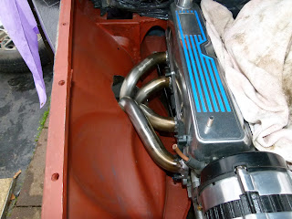
Cutting out the inner wings for the RV8 exhaust manifolds/headers.
I chose to go with the RV8 manifolds in preference to the block hugger type, because they are more efficient and the holes help with cooling the engine bay.
No template was supplied with the manifolds, I guess that's because each installation is slightly different, this made it difficult to know where to make the holes. So I measured the manifolds and made a mark where the center of the exhaust outlet pipe is. then made a rough hole with a Jigsaw.
Broke a few blades cutting the holes, due to the angle and curves.
I chose a Clive Wheatley stainless steel exhaust system, because of his reputation for quality, and the manifolds certainly look well made and fit the engine nicely.
I will tidy up the edge of the holes when the engine comes back out again, which it will have to, to paint the engine bay.
I have made the decision to reinforce the exhaust openings in the wings, although I dont think it totally necessary, I do think it will look better and also keep the MOT people happy.
I made a cardboard template and then them out of new sheet metal, which I will then shape and weld into place.
Once the shapes were cut out with the jigsaw, I shaped them to match the inner wing profiles and then plug welded them into place.
Friday, 1 November 2013
Front inner wings and engine bay repairs:
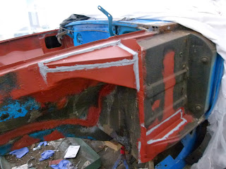
n/s/f inner wing corrosion cut away. a panel made up and welded into place, then the whole repair lead loaded.
The finished inner wing repair, can see the joins!
The throttle pedal bracket had rusted away, you can't buy these, so a new one had to me made from scratch.
n/s/f re-enforcer was repaired with a new panel on the top, and the chassis end repaired with 5 separate pieces on new metal.
Rusty slam panel was wired brushed then treated with Bonda.
n/s/f inner wing corrosion cut away. a panel made up and welded into place, then the whole repair lead loaded.
Bad corrosion on the o/s/f inner wing, and wing top rail, repair panels purchased and welded into place, a flange was made on the edge and plug welded, the the whole seam lead loaded and primed using Bonda Zinc primer.
Extensive corrosion in the o/s/f splash panels and re-enforcers. All rust was cut out and repair panels welded into place.
n/s/f re-enforcer was repaired with a new panel on the top, and the chassis end repaired with 5 separate pieces on new metal.
n/s/f chassis was corroded in a couple of places, so this was welded up.
Subscribe to:
Comments (Atom)


