A Rover 3500 V8 was sourced, and was just a pile of parts, the engine was originally out of an SD1.
I stripped the engine down to the bare block, and examined each component for wear.
Before and after shot of the pistons. with new rings fitted.
The motor was reassembled with new rings, seals and gaskets, a Rover P6 Short Nose water pump fitted and a new oil pump cover with remote pipe take off.
Cleaned cylinder heads.
The exhaust valves could not be saved, they were too pitted to use, so new ones purchased and lapped in.
This is my technique for lapping valves in.
the valves were installed and new stem seals fitted.
The cylinder heads were fitted using composite gaskets, these lower the compression ratio slightly but have better sealing qualities. A composite inlet manifold gasket was also used.
A modified Rover inlet manifold was sourced which will take a Holley 4 Barrel Carburettor.
The bottom pulley was was stripped down so that just the harmonic balancer was left and I then had a machinist put a groove in it for the fan belt. there is no room for the standard bottom pulley set up.
The engine was originally mated to an automatic gearbox, so I removed the spigot bush and fitted a manual box one. The technique of packing the old bush with grease and trying for force it out didn't work on this occasion, so I has to cut it.
Decided to have the flywheel skimmed, because the amount of work involved if I discover clutch judder after installation.
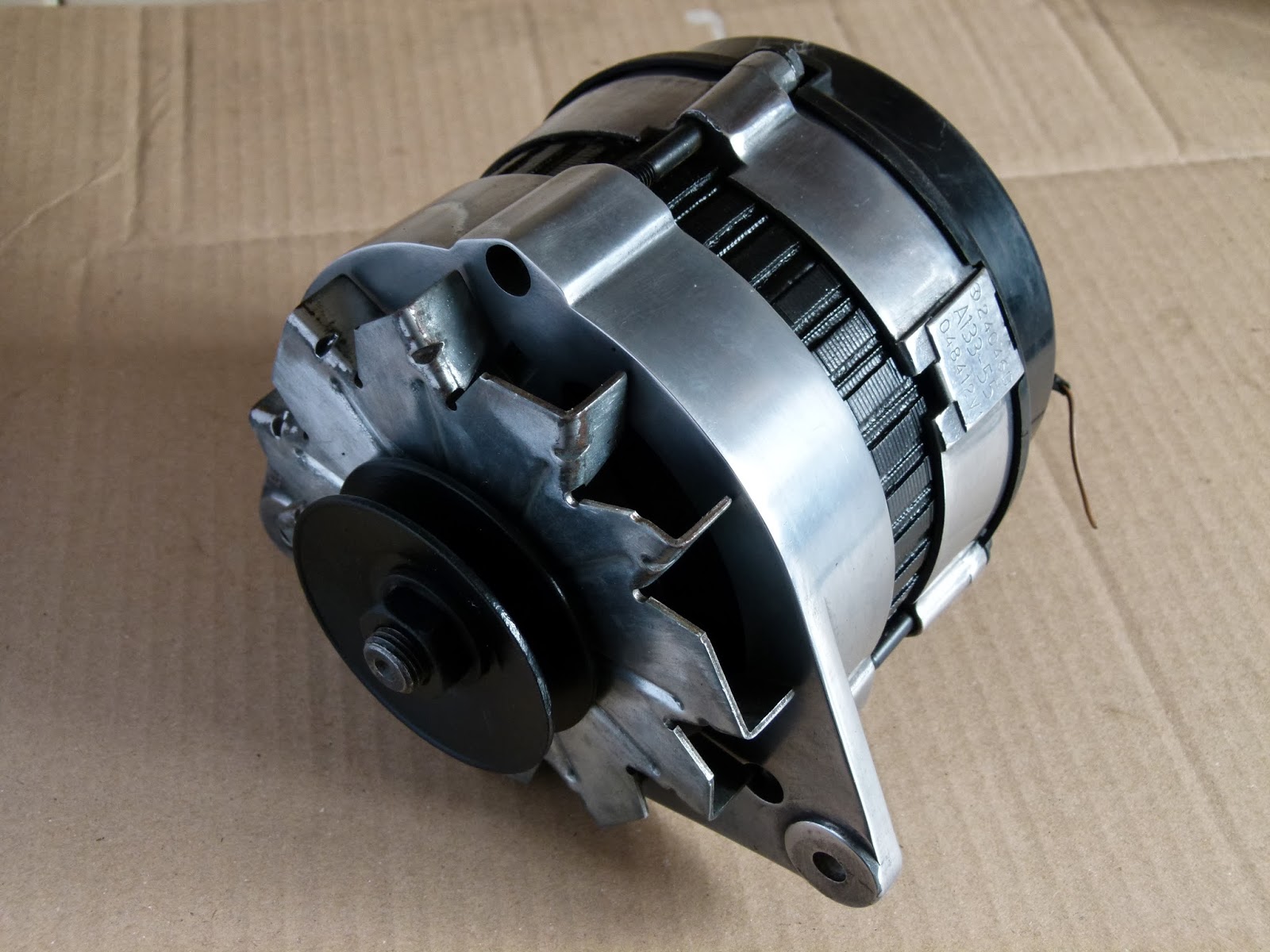
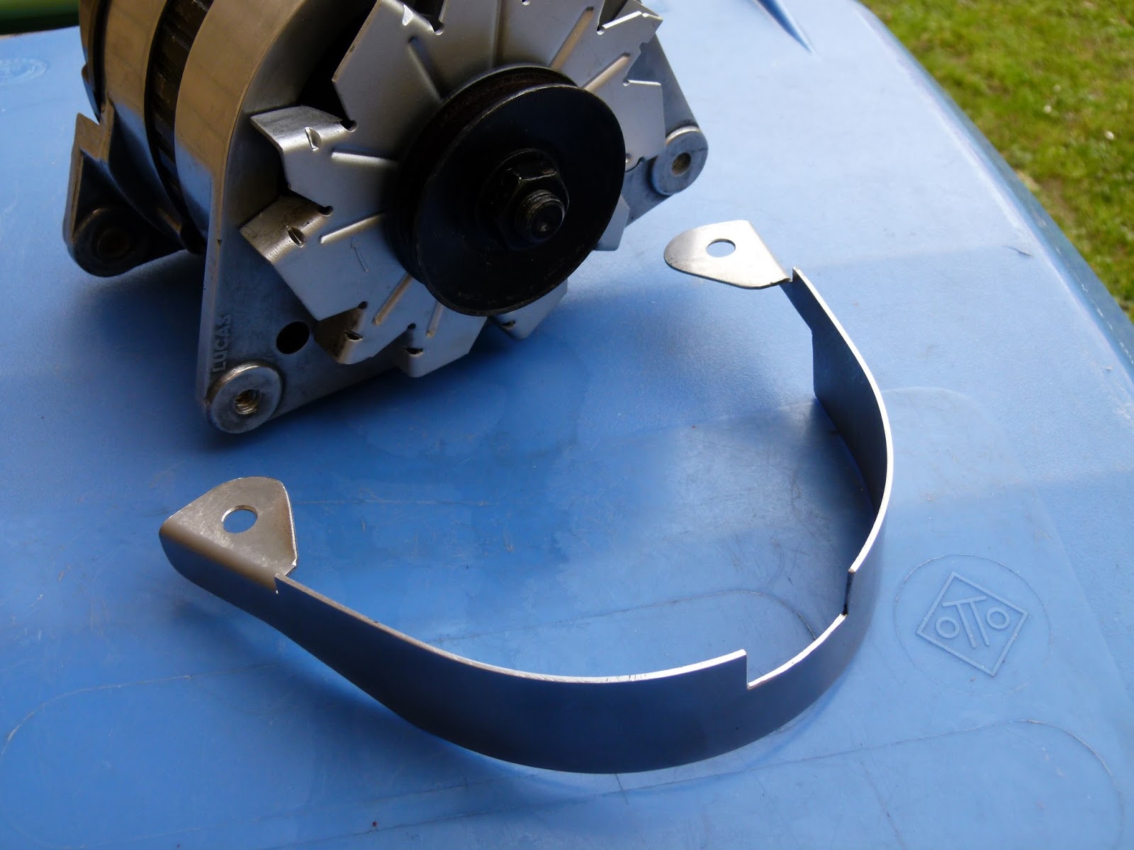
Max did a great job on polishing the rocker covers, being alloy they look great when sanded smooth and polished. The alternator will get the same treatment.
V8 engine mounts fitted.
There doesn't seem to be an agreed way of fitting these, I initially tried it with the bolt low down as in the picture above, but found that they bottomed out on the chassis mount, so I fitted them the other way up and it was a much better fit. Also had to fit a thinner mount on the n/s in an attempt to get the engine to sit down lower, but sadly bonnet clearance is still a problem.
Having now completed all the bodywork and repainted the car, we are ready to put the new V8 into the MGB. A new clutch is fitted first and the the gearbox attached.
Here is the Rover V8 being installed to the MGB. It is best to put it in with the gearbox attached. You have to tilt the unit down at an angle to get it in. Take it slow and make small adjustments, and it should go in. There is not much room for error though.
The stainless steel manifolds are attached and the engine and gearbox mounts fitted.
The cooling system will be upgraded, with a larger V8 radiator, hoses and additional cooling fan. The original heater control valve is used, and connected to the V8 with an extension tube, which is available through the MG owners club, this tube puts the valve further back in the engine bay, so the hoses and cables still fit.
Here is an interesting problem. I purchased a set of three stainless steel oil cooler hoses from MGBHive and the short hose from the filter to the pump is too long, it pushes hard against the inner wing and has a sharp bend in it. I contacted them, but that is the only one they do, so I returned it and then purchased the same part from the MG Owners club, and this one is about 1 1/2 inches shorter and a much better fit.
One of the oil cooler pipes runs very close to the off side chassis, so you need to angle grind a bit off to allow room for the hose.
A new electronic SU Fuel pump fitted, and tested.
The Rover V8 oil system has to be primed before you start it up. You should pack the oil pump gears full of grease or vaseline so that it has something to work with, otherwise it has trouble sucking up the oil initially.
I then removed the distributor and made up a tube with a flattened end to fit onto the oil pump drive, and then spun the pump up with an electric drill.
The oil gauge soon went up to 50psi, so I am happy we have a good oil supply and pressure. The engine is ready to start for the first time.
Started the engine for the first time today. very excited, everyone watching, no pressure!
Engine fired almost straight away, but then stopped, tried again, same thing, pumped the throttle and it kept running, but would only keep going if you pump the throttle. sounds like a fueling problem!
The engine was not getting enough fuel, or too much air, plus it had a strange smell about it, from my motor trade background I think it smells of excessive Hydrocarbons, usually caused by a very weak fuel to air ratio.


Stripped down the carb, cleaned every jet and port, found a blocked idle jet, so thought that was probably it, so refitted the carb and tried again, no different!
Then I tested the inlet manifold by blowing steam down it and looking for leaks, none found, however the flange the carb sits on was warped quite bad, so that could be it. I then spent several hours flatting it off with course wet and dry paper taped to a thick piece of glass.


Refitted everything and tried again, no different ! Oh My God!
I decided to go back to basics and use my 30 years plus motor trade experience to get to the bottom of it. I did some old school diagnostics with vacuum gauges and pressure gauges.
1, Vacuum:
First test was to check the inlet manifold vacuum, the Rover V8 should produce about 15 to 20 inches on idle and 3 to 5 inches on cranking, with the throttle shut. I could not do an idle test, cos it wont idle, so did a cranking test, result was zero vacuum, or at least not enough to register on the gauge. So the engine does not have enough suck to pull fuel from the carb.
2, Compressions:
Next test was engine compression, full throttle and ignition disabled, results were not good, ranging from 70 psi to 120 psi and the rest somewhere in between.
3, Cylinder leakage:
Next test was a cylinder leakdown test, used to do these all the time in the motor trade, but as I do not own a leakage tester I made my own.
Its basically two pressure gauges, one with a regulator and a restrictor in between. I used my paint spraying regulator, connected to my compression tester (with the tyre valve removed), and joined then together with a small connector, which I filled with body filler and then drilled a 1.5mm hole through it, this is an important component as it controls the flow or air so that the second gauge reads any leakage correctly in a controlled way.
My home made tested worked really well, and the results were good, with most cylinders showing at most a 5% leakage.
These results mean that the compression loss, is not down to the valve seats, pistons or head gasket, it can only be a mechanical issue to do with the opening and closing of the valves.
The tappet preload is measured with a pieces of wire of various thicknesses, obviously it is done in situ, not on the bench, this photo is only to show the method.
Hydraulic Tappet preload:
I checked the valve timing again and it was ok, so I started to look at the hydraulic tappets. The Rover V8 tappets have a preload , which is controlled by the valve gear set up being within factory spec. If all is within spec then the tappet piston should be slightly compressed in its casing by 0.50 mm to 1.50 mm. This is measured with the tappet empty of oil and that cylinder on tdc. Mine were all too much, some as much as 2.5mm, doesn't sound a lot does it, but the cylinders that had the worst compression were the furthest out of spec, to be more precise, it was the inlet valves that seemed to be the problem, and more so that the worst cylinders had the biggest variation in preload between its inlet and exhaust tappets. So if you think tappet preload is not important, think again.
Adjustable Pushrods:
There are several solutions to excessive tappet preload, 1, replace everything with new parts, including valves, seats, rockers, tappets etc. 2, Raise the rocker shaft up on shims, but this alters all the tappets by the same amount, no good in my case, because of the large variations. 3, Fit adjustable Pushrods.
I went for option 3, purchased a set of 5/16 adjustable Pushrods from Real Steel.
You have to press fit the bottom ball yourself as they give you two sizes, I selected the correct size, and I had to knock them on with a copper hammer and a piece of hard wood, as I don't own a hydraulic press. I fitted the rods and rocker shafts and then set up the preload. My technique was to wind out the screw gently until all the play had gone, then I calculated that with a thread pitch of 0.80mm, I need to wind the nut out another 1 1/4 turns or 7 1/2 flats, to get top my desired preload of 1.0 mm. I double checked the preload with a Vernier Gauge.
By putting the pointed end onto of the tappet piston and measuring to the top of the tappet outer casing. My tappets with no preload were 2.6mm, so when set up I am looking for 3.6mm on the Vernier.
Cylinder Head modification:
I discovered that the slightly wider Pushrods rubbed against the side of the holes in the cylinder head, so I will need to enlarge these holes.


I
The holes were around 10mm to start, so I drilled them out to around 11.90mm, this was plenty, I had to be very careful to control the swarf, and ensure none entered the engine.
I then refitted everything and tested the compressions again, I got between 140 to 160 psi, not particularly even, but considerably higher that before the preload correction.
I then confirmed that I had some cranking vacuum, which was sufficient, now ready for another start up.
The engine now starts, but still not running as I would like. Some more work is required. It runs rough, and doesn't idle properly. I decided to measure the camshaft timing with a DTI gauge, to satisfy myself that I have not messed up the valve timing when I rebuilt the engine.
I put the DTI on top of number 1 pushrod, and marked up the crankshaft pulley in degrees, I then turned the engine over and measured when the valves started opening (4 thou off fully seated) and again when it closed, I could then calculate the peak cam opening times. I used theses figures to confirm that my valve timing was spot on, and the opening and closing figures similar to a factory camshaft. What I wasn,t expecting though, was considerably more valve lift than standard. I searched the internet with my cam data and found a camshaft that matched my data, turns out it is a Kent Cams, Fast Road Cam (H214).
I now need to use that information to set up the ignition and carb for that camshaft.
In between messing about with the tuning, I fitted a Clive Wheatley Engine Steady Bar.
Sadly I did not manage to get the engine running any sense, so I took the drastic measure of stripping the engine back down again. I then replaced the headgaskets with the Tin type, to get the correct compression ratio back and I fitted a new camshaft (standard 3.5 carb type) and new tappets. I then reset the tappet preload to 1.0mm on the adjustable pushrods.
Original Fast Road cam on the right, Standard 3.5 carb cam on the left.
Once completed I then run the engine at 2500rpm for 20 minutes to break/bed the camshaft in.
The result is amazing, it now runs and idles as it should.


